How to fill holes in an STL file
If you have ever sliced a model only to see a warning about an open mesh, or watched a print start with a section that simply has no surface, you have run into a hole. In an STL, a hole is a gap in the triangle surface where an edge is attached to only one triangle instead of two. This guide walks through why that happens, how to confirm it instead of guessing, and the cleanest way I know to close it — including the free tool on this site.
What a “hole” actually is
An STL stores a shape as a collection of triangles with no structural information beyond their corners and orientation. For the surface to be sealed — the word you usually see is watertight — every edge has to be shared by exactly two triangles. A hole is the opposite: a loop of edges that each belong to a single triangle, forming an open boundary. The slicer has no way to know what is inside that boundary, so it may drop the region, slice through empty space, or refuse the job.
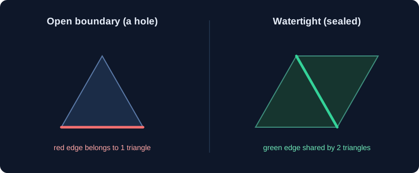
One boundary loop usually means one hole, but a model can carry several separate loops at once. They don't even have to be connected to the same shell: a mesh made of multiple disconnected pieces can have its own boundary on each piece. The count of boundary loops is the number that matters, not the number of triangles near the gap.
Why holes show up in the first place
A missing surface is almost never something you did on purpose. The usual causes are:
- A failed boolean or union. When two solids are combined and the operation does not fully resolve, the contact area can be left open.
- Format conversion. Moving a model between CAD packages and export formats can drop faces, especially on messy or very small geometry.
- Scan or photogrammetry data. A scanner cannot see the far side or occluded areas, so the reconstructed mesh naturally has gaps.
- Aggressive decimation. Reducing triangle count heavily can collapse faces and tear the surface if the simplifier is not constrained.
How to tell whether your model really has one
Don't rely on the 3D preview — a hole can be hidden on the back of the model or on the underside. The reliable signals are:
- Your slicer flags the mesh as open, not watertight, or lists boundary edges.
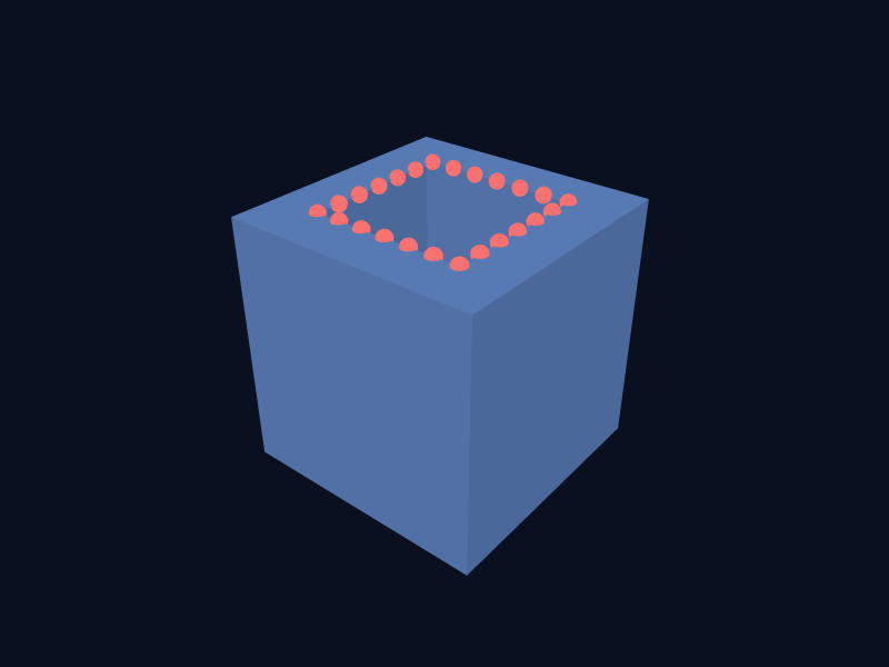
- A mesh analysis reports edges that belong to only one face, grouped into one or more boundary loops.
- A section renders as a see-through gap when you rotate the model and look at it from inside.
If you drop the file into the STL repair tool here, the first thing it does is exactly this analysis, and it lists the boundary loops before you change anything, so you are not fixing blind.
Filling the hole automatically
For most gaps, the practical fix is to let a repair engine triangulate the opening. The engine walks each boundary loop and adds the smallest set of triangles needed to span it, then re-checks that every edge is shared by two faces. That is the approach used on this site, and it runs entirely in your browser through a WebAssembly worker, so the file is read on your machine and never uploaded.
Under the hood, closing a loop is a well-bounded triangulation problem: the rim is a closed chain of vertices, and the engine fills that chain without touching the surrounding faces. A good fill is conservative — it adds only the faces the opening requires rather than rebuilding the whole model.
The workflow is short:
- Open the repair tool and select your STL.
- Read the diagnosis and confirm the holes it found.
- Run the repair. Boundary loops are closed with minimal new faces, and an independent validator re-checks the result.
- Download the sealed STL. The basic tool is free and has no per-file limit.


How to confirm the fill actually worked
Don't just trust a green checkmark. After a repair, the boundary-loop count should read zero, and a strict, independent validator should report the mesh as watertight — meaning every edge now has exactly two faces. Keeping the analysis separate from the repair is deliberate: the same code that fills a hole is not allowed to grade its own homework. If a boundary loop remains, you want to be told plainly rather than handed a file that still fails in the slicer.
Small holes vs. large openings
Size matters, and it is worth being honest about it. A small gap is easy: the new triangles bridge a tight loop and the surface looks essentially untouched. A large opening is different. Filling a wide boundary produces a flat-ish patch that simply spans the rim — it seals the model for printing, but it does not magically reconstruct the curved surface that was missing. If the gap sits on a visible part of the model, inspect the preview before you commit, and expect to do some hand sculpting if the shape matters.
A hole is also not the same as a self-intersection, where two surfaces cross through each other. Sealing a boundary does not resolve crossing faces, and a model with a genuine self-intersection should be reported rather than silently passed. The tool here keeps those cases separate on purpose.
When to repair it by hand instead
Automatic filling is the right default for print preparation, but if the missing area is large or on a feature you care about, manual tools give you control over the new geometry. Desktop mesh editors let you bridge or patch a selected boundary and then sculpt the result. The trade-off is the usual one: more control means more time and a heavier application, whereas an in-browser fill gets you a watertight, printable file in a few seconds.
Wrapping up
A hole is just an open boundary loop, and closing it is a well-defined, reliable operation — far more predictable than fixing self-intersections. If you want the quick path, load your STL in the free tool, confirm the boundary loops, and let it add the minimal faces and re-validate the seal. Just remember to eyeball any large patch, because sealing a gap and reconstructing a missing surface are two different promises.