How to fix non-manifold geometry in an STL
Some mesh errors are easy to spot, like a gaping hole. Non-manifold geometry is the opposite: the model can look perfectly fine in the preview, yet a slicer refuses it because the triangles are connected in a way that does not describe a real solid. This guide explains what non-manifold actually means, the two forms it takes, and how a repair engine resolves it — including the free tool on this site, and an honest look at what the fix does and does not do.
What “non-manifold” means
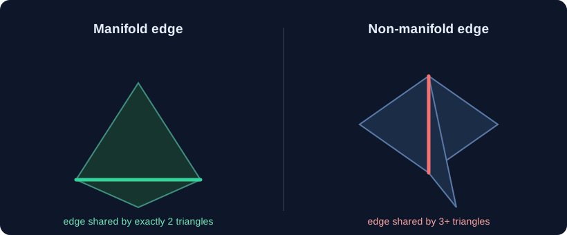
A valid triangle mesh describes a surface you could physically exist on: every edge is shared by exactly two triangles, and around any vertex the faces form a single, unbroken ring. A mesh with that property is called manifold. Non-manifold geometry breaks that rule, and it shows up in two distinct ways:
- A non-manifold edge. An edge that is shared by three or more triangles instead of two. The classic case is several surfaces meeting along one line, like a set of walls fanning out from the same edge. There is no single “inside” and “outside” along that edge, so the solid is ambiguous.
- A non-manifold vertex. A vertex where several faces meet in a way that does not form one clean ring — for example, two separate solids touching only at a single point. Locally the triangles are fine, but the topology around that vertex is not a continuous surface.
Why it matters even when the preview looks fine
A 3D preview just draws the triangles, so overlapping or fanned faces look normal on screen. The problem is mathematical. A slicer has to decide, for every point in space, whether it is inside or outside the model in order to build toolpaths. Around a non-manifold edge or vertex there is no consistent answer, so the slicer may skip the region, produce a broken slice, or reject the file outright. That is why the error often appears only at the slicing stage, after the model already looked “done.”
Where non-manifold geometry comes from
It is almost always a modeling or conversion artifact rather than something you drew deliberately:
- A failed boolean or merge. Combining solids that only touch along an edge, or at a point, leaves the contact area non-manifold.
- Internal or duplicate faces. Extra surfaces left inside a model can share an edge with the outer shell and push it past two faces per edge.
- Joining separate meshes without unioning them. Grouping two objects that merely touch at a vertex keeps them topologically separate at that point.
- Export or conversion issues. Moving between formats and CAD tools can introduce T-junctions or merged faces that break the clean ring around a vertex.
How to detect it instead of guessing
Rotating the model in the preview will not reliably reveal it. The dependable signals come from a mesh analysis: counts of non-manifold edges and non-manifold vertices, plus the overall manifold flag. When you load a file into the STL repair tool here, it runs that analysis before you change anything and reports the counts up front, so you know exactly what you are dealing with rather than clicking repair on faith.

How a repair engine fixes it
The fix for non-manifold topology is fundamentally a split, not a fill. The engine finds the offending vertices and edges, then separates the faces so that each edge ends up belonging to exactly two triangles. Where several surfaces were fanning out from one edge, the shared vertices are duplicated so each surface gets its own copy. After the split, the engine re-checks that the non-manifold edge and vertex counts have dropped to zero and that the manifold flag is now true.
On this site that whole pipeline runs in a WebAssembly worker inside your browser, so the file is read and repaired on your machine and never uploaded. The workflow is short: open the repair tool, select your STL, read the diagnosis, run the repair, and download the result. The basic tool is free with no per-file limit.

Be honest about what the split produces
This is the part worth understanding clearly. Splitting a non-manifold edge removes the topological ambiguity, but it does not merge the surfaces into a sealed solid. On the test mesh above, the repair reports zero non-manifold edges and a manifold result, yet the three walls are now three separate connected components with open boundaries — they are individually valid surfaces, but they are not a watertight solid. That is the correct outcome for a model made of fanned open walls: the engine cannot invent the faces that would join them, and it would be dishonest to pretend the result is sealed.
For a typical solid model, the same split operation usually separates stray internal or duplicate faces from the outer shell, which is exactly what you want. But you should always read the post-repair report: if the boundary-loop or component count is higher than expected, the file is manifold but not necessarily watertight, and you may need to remove the extra pieces or close the remaining boundaries.
How this differs from a hole
Non-manifold topology and a hole are different errors with different fixes. A hole is an open boundary where an edge belongs to only one face, and the fix is to add triangles that fill the gap. A non-manifold edge has the opposite problem — too many faces share an edge — and the fix is to split them apart. Treating one as the other makes the model worse, which is why the analysis step names the exact error rather than lumping everything under a generic “repair” button.
When to fix it by hand
Automatic splitting is the right default for cleaning up a file, but if the non-manifold area sits on geometry you care about, a desktop mesh editor gives you control over which faces to separate and how to rejoin them. The trade-off is the usual one: manual control takes more time and a heavier application, while an in-browser repair resolves the topology in seconds and tells you plainly if the result is still open.
Wrapping up
Non-manifold geometry is a connectivity error — edges with too many faces, or vertices where the faces do not form one ring — and it is fixed by splitting the topology apart until every edge belongs to exactly two triangles. If you load your STL in the free tool, you get the exact counts first and a re-validated result afterward. Just remember to check the component and boundary counts after the split: a manifold result and a watertight solid are two different claims, and a good tool tells you which one you actually have.